Views: 0 Author: Site Editor Publish Time: 2026-09-11 Origin: Site

High-precision water quality probes are completely useless if an incompatible or inadequate display unit bottlenecks the data. Investing in premium sensors means little when they connect to substandard screens. The terminal ultimately dictates the true value of your collected field data. Many facility managers treat the terminal as a minor afterthought during system design. This oversight leads directly to severe signal degradation, frustrating integration failures, and restrictive vendor lock-in. When components mismatch, you face constant troubleshooting instead of experiencing smooth, reliable operation.
We provide a vendor-neutral, engineering-focused framework here. You will learn to evaluate and match the correct water quality display terminal to your existing or planned sensor arrays. This guide ensures seamless data flow and robust system performance. Following these principles will help you build a resilient, future-proof monitoring architecture.
Protocol compatibility (Analog vs. Digital/Modbus) is the non-negotiable first filter for matching probes and terminals.
Selecting a multiparameter sensor display over single-channel units requires careful attention to interface complexity.
Industrial compliance (e.g., EPA reporting standards) requires terminals featuring built-in data logging, audit trails, and secure SCADA integration.
Avoid proprietary lock-in by prioritizing controllers supporting open-source communication protocols.
Physical connections and software protocols form the critical communication bridge. They represent the most common failure points in system integration. A mismatched signal turns expensive sensors into useless plastic. Establishing a flawless handshake between your sensor and terminal guarantees data integrity.
Legacy systems heavily rely on analog signals like 4-20mA or 0-5V. These provide broad legacy support across many industries. You will find them relatively straightforward to troubleshoot using a standard multimeter. However, analog signals remain highly susceptible to electrical noise. Long cable runs often degrade the signal accuracy significantly. Ground loops can easily skew your critical parameter readings.
Digital sensors utilizing RS485 or Modbus RTU represent the standard for modern installations. They enable efficient daisy-chaining of multiple devices. You get reliable, long-distance data transmission over hundreds of meters. Furthermore, digital protocols deliver multi-variable data from a single probe. One digital sensor might transmit pH, temperature, and diagnostic health simultaneously. This capability drastically reduces wiring complexity.
Closed-loop systems pose significant long-term risks. In these restrictive setups, a specific sensor display meter only reads proprietary brand probes. If the manufacturer discontinues a probe, you must replace the entire system. You lose negotiating power when buying replacement parts.
Universal controllers offer much more operational flexibility. They allow you to mix and match the best sensors for your specific application. Request the Modbus register map from vendors before purchasing any new equipment. This simple action verifies true interoperability. It ensures the terminal can correctly interpret the sensor's specific data registers.
Best Practice: Always request a demonstration connecting a third-party sensor to the proposed terminal.
Common Mistake: Assuming all RS485 ports communicate using the exact same Modbus language.
Aligning terminal capacity requires balancing site scalability alongside strict budget constraints. You must evaluate your current needs while anticipating future regulatory expansions. Under-sizing your terminal leads to costly hardware replacements later.
These dedicated units excel for isolated, mission-critical measurements. A standalone pH dosing station serves as a perfect prime example. They offer a noticeably lower upfront cost. Operators also benefit from a much simpler, highly focused interface. Training new staff on these devices takes mere minutes.
Single-parameter units shine in environments demanding absolute simplicity. However, their physical footprint expands rapidly if you need to monitor multiple parameters later. Installing five individual controllers consumes valuable wall space and increases wiring complexity.
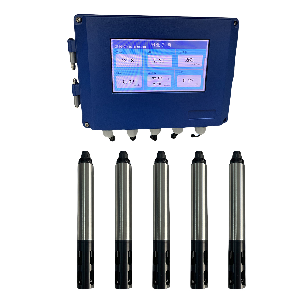
These advanced units are essential for comprehensive environmental monitoring. You can track dissolved oxygen, turbidity, pH, and conductivity simultaneously. A high-quality multiparameter sensor display simplifies complex data streams beautifully. It centralizes all calibration and monitoring tasks into one hub.
Assess the UI/UX rigorously during your evaluation phase. Can operators read all critical parameters at a glance? They should never navigate buried menus during an active chemical spill. High-contrast screens and intuitive navigation buttons dictate daily usability. Touchscreens work well indoors but often fail in wet, outdoor environments.
A high-end water probe controller does far more than just display numbers. It acts as the intelligent edge-decision maker for plant operations. The system transitions from passive observation into active facility management. It automation reduces human error and speeds up response times.
Programmable relays manage your most critical automated tasks effectively. They trigger local alarms, run chemical dosing pumps, and activate emergency aerators. You must verify the terminal offers enough independent relays for your specific process.
PID (Proportional-Integral-Derivative) control capabilities are absolutely necessary for chemical treatment. Simple on/off relays often cause severe over-dosing. A PID controller calculates the exact chemical volume needed based on real-time changes. This prevents massive pH swings and saves expensive treatment chemicals.
Proportional: Adjusts dosing based on current error size.
Integral: Corrects long-term steady-state offsets.
Derivative: Anticipates future errors based on the rate of change.
You must match the terminal's enclosure to the actual deployment environment. Installing standard indoor equipment outside guarantees rapid hardware failure. Moisture, dust, and corrosive gases destroy sensitive electronics quickly.
Rating Type | Protection Level | Ideal Application Scenario |
|---|---|---|
IP54 / NEMA 3 | Dust protected, resists splashing water | Indoor control rooms, clean manufacturing floors |
IP65 / NEMA 4 | Dust tight, resists low-pressure water jets | Outdoor installations, standard washdown zones |
IP67 / NEMA 4X | Immersion up to 1m, corrosion-resistant | Harsh chemical plants, marine environments |
Modern industrial operations treat monitored data as legally binding evidence. An effective online monitoring terminal supports strict regulatory compliance effortlessly. It helps facilities meet rigorous SOPs and local environmental reporting standards. Lost data often results in massive fines from regulatory bodies.
Assess onboard memory capabilities carefully during your selection process. You need robust SD card slots or USB export options. These physical storage methods provide essential offline audit trails. If your network fails, the local memory prevents permanent data loss.
Evaluate IoT capabilities for convenient remote dashboard access. Options like 4G/LTE, Wi-Fi, and LoRaWAN ensure continuous data visibility. Remote telemetry allows managers to monitor plant health from anywhere. It dramatically reduces emergency late-night visits to the facility.
Ensure the terminal features standard industrial outputs for higher-level systems. Isolated 4-20mA, Modbus TCP/IP, and Profibus represent accepted industry standards. They seamlessly feed central facility PLCs for unified, plant-wide control.
Modbus TCP/IP provides exceptional speed over standard Ethernet networks. It allows your central SCADA system to pull data from dozens of terminals simultaneously. Always verify your IT department supports the terminal's specific network protocols.
Implementation realities often introduce unexpected, costly friction points. Proper planning mitigates these rollout challenges effectively. Treat the terminal integration as a dedicated engineering project, not a simple purchase.
Does the terminal allow for intuitive, on-site multi-point calibration? Avoid units demanding complex manual entry or calculation. Technicians calibrating sensors in harsh weather need streamlined, automated workflows. The terminal should auto-recognize standard buffer solutions instantly.
The terminal should store a detailed calibration history permanently. It must also track sensor health diagnostics accurately. Tracking slope degradation over time supports proactive, predictive maintenance. You replace sensors right before they fail, rather than after.
Follow this exact sequence to ensure integration success:
Audit existing probe outputs: Document every signal type (Analog, RS485, SDI-12) currently in use.
Define parameter counts: Map current needs and add 20% capacity for optimal future scalability.
Map output requirements: Count the required relays, analog re-transmissions, and digital SCADA connections.
Verify physical constraints: Check environmental ratings, mounting styles (panel vs pipe), and available power supplies.
Matching equipment serves as an essential exercise in strategic future-proofing. The right display terminal acts as the scalable, intelligent brain of your entire architecture. It transforms raw electrical signals into actionable, compliance-ready data.
Take strict inventory of your current probe specifications today. Consult original engineering data sheets to verify full Modbus compatibility. Map out your exact control and telemetry requirements carefully. Complete these preparatory steps before requesting any vendor demos or trials.
A: Yes, you can bridge this gap using analog-to-digital converters. You might also select a terminal featuring mixed input boards. However, you must test signal fidelity thoroughly before full deployment. Analog signals remain prone to interference during conversion.
A: It depends entirely on your specific system architecture. Smart digital probes store calibration data internally. The terminal merely reads and displays this information. Analog probes rely completely on the terminal itself to store the complex calibration curve.
A: Analog 4-20mA signals are typically reliable up to 100 meters. This distance depends heavily on utilizing high-quality, shielded cables. Digital RS485 connections can reliably transmit accurate data up to 1,000 meters without experiencing any noticeable signal degradation.