
Views: 0 Author: Site Editor Publish Time: 2026-09-19 Origin: Site


Engineers often overlook the housing surrounding their analytical probes. However, an improperly sized flow cell turns a high-end sensor into a severe process liability. This oversight quickly causes delayed response times, false readings, or premature probe failure. Moving from lab-based batch sampling to reliable continuous inline monitoring requires strict fluid control. Without exact dimensions, your monitoring loop simply generates unpredictable noise. Poor fluid dynamics will constantly distort your process variables and ruin your automation loops. This article provides a straightforward, evidence-based framework for your system. We will cover how to calculate critical dimensions, select appropriate housing materials, and integrate everything smoothly. You will learn to size and configure a reliable chamber for any industrial process loop.
Internal volume directly dictates response time: Smaller volumes respond faster but require strict flow rate control to prevent pressure-induced sensor damage.
Flow velocity is a balancing act: Velocity must be high enough to prevent particle settling and biofouling, but low enough to avoid cavitation and signal noise.
Material dictates longevity: The chemical makeup, temperature, and pressure of the sample fluid must govern whether you use acrylic, PTFE, PVC, or 316L Stainless Steel.
Installation orientation impacts accuracy: Proper bypass loop design and vertical fluid routing are non-negotiable for mitigating trapped air bubbles.
Oversized chambers create dangerous stagnant zones. Fluids linger inside the chamber instead of refreshing immediately. This creates a significant time lag. If your process relies on real-time dosing, delays are catastrophic. Consider a wastewater pH neutralization facility. The dosing pumps rely entirely on sensor feedback. If a large chamber creates a one-minute delay, the pumps keep injecting acid. The tank becomes dangerously acidic before the sensor registers the change. A 30-second lag leads to costly chemical overdosing. This overshoot requires extra caustic chemicals to correct. It creates a chaotic, oscillating control loop and severe regulatory non-compliance.
Undersized chambers create the exact opposite issue. High flow rates force water violently against the probe. Fast fluid causes scouring on delicate optical lenses. It quickly strips away the sensitive gel layers from pH probes. Fast currents also actively pull potassium chloride out of the reference junction. This rapid depletion shortens the lifespan of reference electrodes significantly. This degradation ruins the instrument over time. You will also notice highly unstable analytical readings. Fast currents introduce mechanical noise into the electrical signal, forcing you to constantly replace expensive probes.
Poor fluid dynamics inevitably cause frequent fouling. Stagnant corners allow suspended solids to settle. Scaling minerals like calcium carbonate adhere easily to low-velocity surfaces. Algae and biofilms thrive in these low-velocity pockets. Once a biofilm establishes itself, it creates a micro-environment over the sensor tip. The probe starts reading the biofilm's chemistry instead of the bulk fluid. This forces technicians to constantly pull the probe from the line. They must perform manual cleaning routines weekly or even daily. This labor burden drains facility resources and completely defeats the purpose of automated monitoring.
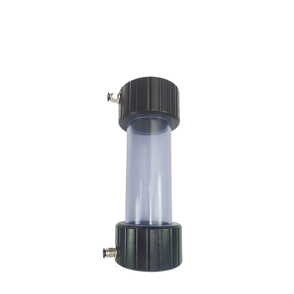
Sizing an inline sensor chamber requires precision and a clear understanding of process goals.
You must balance the internal volume against your target response time. The formula is straightforward. System Response Time equals Internal Volume divided by Flow Rate. Smaller internal volumes yield much faster refresh rates. However, different analytical parameters tolerate different lag times. Dissolved oxygen (DO) sensors demand rapid turnover to track biological processes accurately. Conductivity sensors can often tolerate slightly slower refresh rates without harming process control. You must map these requirements before selecting a housing.
Sensor Type |
Acceptable Lag Time |
Recommended Volume |
Target Flow Rate |
|---|---|---|---|
Dissolved Oxygen (DO) |
< 5 seconds |
Low (10-30 mL) |
High (400+ mL/min) |
pH / ORP |
10-15 seconds |
Medium (30-50 mL) |
Moderate (200-400 mL/min) |
Conductivity |
20-30 seconds |
High (50-100 mL) |
Low (100-200 mL/min) |
Velocity must stay within a specific functional range. You want enough speed to maintain a self-cleaning action. This prevents debris accumulation on the sensor tip. However, excessive velocity causes flow-induced noise and turbulent cavitation. Turbulence introduces microscopic air pockets that hit the measurement tip. This causes wild fluctuations on your transmitter screen. Keeping the flow laminar ensures a smooth, predictable fluid stream. We recommend specific flow rates based on your process tubing. For standard 1/4" tubing, aim for 200 to 500 mL/min. For larger 1/2" tubing, scale up your flow to 1 to 2 L/min. This sweet spot provides cleaning action without destructive turbulence.
Temperature and maximum allowable pressure share an inverse relationship. As fluid temperature increases, plastic housings lose structural integrity. Their pressure ratings drop significantly. A PVC chamber rated for 100 PSI at room temperature might only handle 30 PSI at 140°F. You must map this derating curve for your specific material choice. Furthermore, sudden process pressure spikes will shatter sensitive glass pH electrodes. They can also permanently rupture thin dissolved oxygen membranes. We strongly recommend installing pressure-reducing valves (PRVs). Place these valves just before the water sampling flow cell. This protects your analytical investment from unexpected pipeline surges.
The chemical makeup of your fluid dictates your housing material choice entirely.
Stainless Steel (316L): This metal handles high temperatures and extreme pressures effortlessly. It resists general organics and solvents quite well. However, it remains highly vulnerable to high chlorides and harsh salts. These ions cause rapid pitting corrosion in stainless steel over time.
PTFE/Teflon: This fluoropolymer is the industry standard for aggressive acids. It withstands harsh solvents perfectly without degrading. Unfortunately, it is often cost-prohibitive for standard municipal water applications. You reserve PTFE for the most demanding chemical environments.
CPVC/PVC: These rigid plastics offer exceptional cost-effectiveness. They work perfectly for standard municipal water and cooling tower loops. They are also ideal for low-temperature industrial wastewater streams.
Sometimes operators need to see the sensor tip directly during operation. Visual inspection helps identify trapped bubbles or rapid fouling instantly. This transparency is strictly crucial for turbidity and colorimetric sensors. In these specific cases, you must specify clear acrylic or polycarbonate materials. Acrylic offers excellent optical clarity for routine manual inspections. Just ensure your fluid chemistry does not degrade or cloud the clear plastic over time. Harsh industrial solvents will quickly turn clear acrylic into a milky, opaque mess.
The main body is only as robust as its internal seals. A premium stainless housing will still leak if the O-rings fail chemically. You must meticulously match the elastomer to your fluid chemistry. Viton works exceedingly well for many mineral acids and industrial oils. EPDM is highly preferable for caustic bases and hot water applications. Kalrez offers extreme chemical resistance for harsh industrial solvents. Always verify specific elastomer compatibility charts before finalizing your loop design.
Proper online probe installation minimizes operational risks and eliminates long-term maintenance headaches.
We strongly advise against installing sensitive analytical sensors directly into main process lines. Direct installation makes routine maintenance dangerous, difficult, and disruptive. Instead, utilize a dedicated slip-stream or bypass loop configuration. This architecture pulls a very small sample stream from the main pipe. It routes the fluid through the chamber and returns it safely downstream. You must include robust isolation valves on both the inlet and outlet. This allows technicians to safely isolate and remove the probe for calibration without shutting down the entire plant.
Fluid routing orientation is a non-negotiable design factor. The fluid must enter from the bottom port. It must exit from the top port. This vertical flow path naturally purges trapped air bubbles. Air bubbles clinging to the sensor tip cause erratic analytical spikes. A bottom-up approach pushes bubbles out automatically. It guarantees the sensor stays fully submerged in liquid at all times, ensuring stable contact with the fluid.
Main-line process pressure fluctuates constantly during daily facility operations. Pumps turn on and off, changing the flow dynamics instantly. You must shield your sensor loop from these destructive variations. Integrate precision rotameters or adjustable needle valves upstream of the chamber. These devices help you maintain a constant, verifiable flow rate locally. Consistent flow prevents undue mechanical stress on the probe tip. It also ensures your response time calculations remain accurate and predictable throughout the day.
Deciding between a custom build and a standard water sensor flow cell shapes your project budget and maintenance timeline.
Standardized COTS solutions fit most normal industrial monitoring applications perfectly. They perfectly accommodate the standard 12mm or 25mm PG13.5 analytical probes used globally. Choosing a commercial option significantly lowers your upfront engineering costs. It also guarantees immediate availability of standard replacement parts. If a housing cracks during a night shift, you can order a standard replacement overnight. This completely minimizes facility downtime during unexpected maintenance events. Standard units just make financial sense for most manufacturing plants.
Certain projects demand entirely custom engineering and fabrication. You might need this for specialized scientific applications or pilot plants. Extremely low sample volumes often require intricate microfluidic designs. Multi-parameter sensor blocks also necessitate custom CNC machining from solid plastic blocks. Non-standard form factors require unique housing dimensions that suppliers do not stock. However, custom builds carry significant project trade-offs. You must account for long manufacturing lead times. You must also specify exact machining tolerances to avoid catastrophic leaks.
Before finalizing any purchase, prepare a clear specification list. Hand this checklist directly to your supplier:
Maximum System Pressure/Temp: State the absolute peak thermal limits and pressure spikes your system will experience.
Precise Sensor Thread/Dimensions: Provide the exact insertion depth and thread pitch (e.g., PG13.5) of your probe.
Target Flow Rate Range: Define the minimum and maximum acceptable flow in mL/min or L/min.
Sizing an analytical flow cell is fundamentally an exercise in practical fluid dynamics. It requires careful risk mitigation at every single step of the design phase. It is not just about finding a cheap pipe fitting that threads correctly. You must balance internal volume, flow velocity, and material compatibility perfectly. Investing engineering time in exact sizing prevents years of erratic data. A proper bypass loop design prevents frequent, expensive sensor replacements. It stabilizes your entire automated monitoring architecture. We highly recommend verifying your baseline assumptions before ordering expensive parts. Consult your sensor manufacturer’s specific dimensional drawings carefully. Speak with an experienced integration specialist to verify your system calculations today. A well-designed flow-through sensor system pays for itself rapidly through reliable, continuous data.
A: The most effective method is utilizing a bottom-up flow orientation. Plumb your system so fluid enters the bottom port and exits the top. This vertical path naturally sweeps air bubbles upward and out of the chamber. Additionally, installing a slight backpressure valve on the outlet prevents dissolved gases from breaking out of the solution.
A: Connection sizes vary based on industrial standards. For the process pipe connections, NPT and BSP threads are the most common. For the analytical probes themselves, the PG13.5 thread is the dominant global standard for 12mm sensors. Some heavy-duty industrial probes utilize 3/4" or 1" NPT threads instead.
A: Yes, grounding is often critical, especially in plastic housings. Flowing water generates static friction inside PVC or PTFE chambers. This stray electrical current interferes with sensitive pH or ORP readings. You should install a solution ground or earth contact pin within the fluid stream to ensure stable analytical readings.
A: Cleaning frequency depends entirely on your sample turbidity and flow velocity. Clean drinking water lines may only require bi-annual maintenance. Conversely, industrial wastewater streams often demand weekly cleaning. We recommend establishing strict visual inspection protocols. Check clear housings regularly to spot early biofilm growth before it impacts your data.


