Views: 0 Author: Site Editor Publish Time: 2026-09-03 Origin: Site

Deploying a continuous monitoring system requires more than just dropping a sensor into a body of water. A misconfigured setup leads to data gaps and frequent maintenance trips. For project managers and environmental engineers at the decision stage, the challenge is not just finding sensors. You must integrate probes, power, and telemetry into a cohesive package. This package must survive harsh aquatic environments while delivering accurate data.
This guide breaks down the essential components of a reliable platform. We cover implementation realities you should anticipate before launch. We also provide a framework for evaluating vendors and hardware ecosystems. You will learn how to design a sustainable platform tailored to your specific environmental data needs.
A functional buoy package requires balancing the power budget among the multiparameter water probe, data logger, and telemetry system.
Biofouling mitigation (e.g., mechanical wipers, copper guarding) is a mandatory investment, not an optional upgrade, for sustained data accuracy.
Telemetry selection dictates your power requirements; Cellular/LoRaWAN systems fit near-shore projects, while Satellite is required for remote deployments.
Selecting a vendor should hinge on ecosystem compatibility, TCO over a 3-to-5-year lifecycle, and transparent calibration requirements.
You must build your monitoring platform on a solid physical foundation. A reliable water quality monitoring buoy relies on four non-negotiable pillars. These essential components include the physical floatation platform, the sensor payload, the power supply, and the data transmission unit. If any single pillar fails, the entire system becomes effectively useless.
Every deployment requires carefully balancing payload capacity against physical stability. Adding more measurement instruments increases the total weight. It also creates additional hydrodynamic drag underwater. You might feel tempted to attach oversized solar panels or heavy telemetry masts to secure better connectivity. However, these additions shift the center of gravity upward.
Top-heavy buoys are highly prone to tipping over during high winds or turbulent surface currents. Field engineers understand you must maintain a low center of gravity. You should distribute battery weights evenly at the lowest possible point inside the buoy hull. Proper weight distribution prevents the platform from capsizing when subjected to severe wave forces. A capsized buoy instantly submerges telemetry antennas, destroying your transmission capabilities and potentially flooding unsealed battery compartments.
Selecting the right sensors dictates the ultimate value of your data. Standard environmental compliance typically requires a core baseline suite of measurements. You generally need Temperature, pH, Dissolved Oxygen (DO), Conductivity or Salinity, and Turbidity. These core metrics form the fundamental baseline for almost all environmental impact studies.
Application-specific projects require highly targeted sensor add-ons. For comprehensive algae and nutrient tracking, you will need specialized fluorometers. Chlorophyll-a and Phycocyanin sensors are crucial for detecting harmful algal blooms before they escalate. In aquaculture environments, precision matters greatly. Shrimp or fish farming operations require high-accuracy optical dissolved oxygen probes. They also depend heavily on specific ion sensors, such as Ammonia or Nitrate detectors, to prevent catastrophic fish kills.
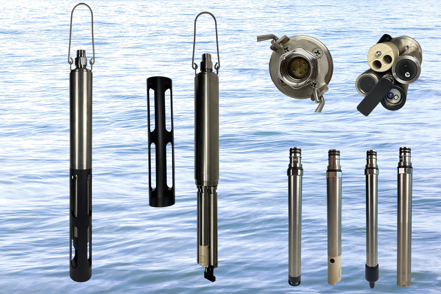
You must decide between using a single aggregated multiparameter water probe or deploying individual modular instruments. An aggregated probe simplifies your physical integration. It uses a single communication cable and requires less mounting hardware. Conversely, modular sensors allow for targeted replacements if one specific probe fails. While modular setups offer replacement flexibility, they inherently increase the total number of underwater connections and potential leak points.
Never treat any measurement instrument as a "set-and-forget" device. Sensor drift is entirely inevitable in harsh aquatic deployments. You must conduct a thorough risk assessment regarding maintenance schedules. Establish clear expectations for baseline calibration intervals before deploying your hardware.
The following table outlines common measurement technologies and their respective field maintenance expectations.
Sensor Category | Drift Risk Level | Recommended Baseline Calibration Interval |
|---|---|---|
Temperature & Conductivity | Low | Every 3 to 6 months |
Optical Dissolved Oxygen (DO) | Low to Medium | Every 2 to 3 months |
Electrochemical pH / ORP | High | Every 3 to 6 weeks |
Optical Turbidity / Fluorometers | Medium (Highly dependent on biofouling) | Every 4 to 8 weeks |
Ion Selective Electrodes (Ammonia/Nitrate) | Very High | Every 2 to 4 weeks |
Your telemetry selection directly drives your daily power consumption. Matching your data transmission method to your physical location is vital for sustainable remote water monitoring. Choosing the wrong transmission protocol guarantees premature battery death and lost data.
Cellular networks like 4G, LTE, and 5G work best near populated areas. They easily handle high-frequency, large-packet data transmissions. However, cellular modems draw significant amounts of power during each connection cycle. They constantly ping local towers to maintain signal integrity.
LoRaWAN or localized radio systems offer the lowest overall power draw. They are ideal for private, localized networks. You might use a LoRaWAN architecture for a multi-buoy array deployed across a single large aquaculture facility. These systems send small packets of data over line-of-sight distances very efficiently.
Satellite telemetry becomes absolutely mandatory for highly isolated locations. If you monitor deep offshore zones, you must rely on satellite uplinks. Satellite modems carry a high cost per byte of data. They also introduce higher data latency and demand substantial burst power to reach orbital receivers.
Calculating your power budget requires brutal realism. You must use a specific operational formula. Calculate your continuous sensor draw, add your telemetry transmission frequency, and include your mechanical wiping frequency. This combined total equals your required daily Amp-hours (Ah) of energy.
Never completely trust the optimal solar ratings published on manufacturer spec sheets. Always calculate your energy budget for the absolute worst-case scenario. You must account for consecutive days of heavy cloud cover. Factor in low winter sun angles, which drastically reduce solar yield. Finally, anticipate the inevitable efficiency loss caused by salt spray, bird droppings, and natural solar panel degradation over time.
Marine growth quickly destroys analytical accuracy. Biofouling represents the single biggest cause of data failure in the field. Marine environments and nutrient-rich freshwater lakes face severe algae, barnacle, and biofilm proliferation. A clean sensor lens can become completely obscured in less than fourteen days.
You must implement aggressive mitigation strategies to protect your hardware. Deployment location on the buoy matters significantly. Central deployments utilize a through-hull deployment pipe. This central pipe shields your probes from floating debris and direct sunlight. Conversely, side-mounting exposes your buoy water sensors to direct wave impact. Side-mounting also increases ambient light exposure, which rapidly accelerates local algae growth.
Field experts rely on layered defense mechanisms against biofouling. We categorize these into active and passive methods.
Active Mitigation: This involves motorized, moving parts. Central mechanical wipers periodically sweep the main sensor faces. Localized sensor brushes clean individual optical lenses before every reading.
Passive Mitigation: This utilizes chemical or physical deterrents. Copper mesh wrapping physically limits organic attachment around the probe body. Specialized anti-fouling paint protects the outer buoy hull. Some advanced systems use targeted UV light emission to prevent initial biofilm formation on optical windows.
Deployment poses distinct physical engineering challenges. Cable entanglement easily destroys expensive probes. You must select an appropriate mooring design for your local current conditions. A single-point mooring allows the buoy platform to swing freely, but it risks spinning the payload. Two-point mooring provides much greater directional stability in high-flow rivers. A robust, well-tensioned mooring line prevents underwater cables from wrapping around the heavy anchor chain.
Do not blindly purchase a locked, proprietary system. Open architecture is critical for long-term viability and operational flexibility. You must ask if the central data logger can accept third-party hardware. Your platform should effortlessly support standard industry communication protocols.
Ensure your chosen logger guarantees compatibility with SDI-12, RS-485, and Modbus outputs. These protocols ensure you can integrate various instruments over time. Proprietary ecosystems lock you into single-source hardware replacements. Open architecture empowers you to swap out failing probes with better alternatives later. This flexibility is essential for continuous surface water monitoring.
Vendor vetting requires asking difficult, evidence-based questions. Focus heavily on verifiable hardware reliability and practical field support.
Hardware Reliability: Request hard data on the Mean Time Between Failures (MTBF) for both the logger and the telemetry modem.
Software Usability: Evaluate the vendor's calibration software interface. Does it offer an intuitive mobile application, or does it require expensive, specialized training courses for field technicians?
Logistical Support: Confirm realistic hardware implementation timelines. Ask explicitly about the availability of local field support and regional replacement parts.
A successful environmental deployment requires rigorous, proactive risk mitigation. You must balance your ideal data requirements against uncompromising physical power limitations. Biofouling realities will ultimately dictate your field maintenance schedule, no matter what hardware you choose.
Start by firmly documenting your absolutely mandatory measurement parameters. Calculate the exact connectivity constraints of your specific deployment site before selecting a telemetry modem. Request comprehensive lifespan and longevity models from your shortlisted vendors. Look well beyond the initial hardware quote to understand the true sustainability of the monitoring platform. Proper planning ensures your system delivers continuous, high-quality data year after year.
A: Calibration frequencies range from every three to eight weeks. The exact timeline depends heavily on your specific deployment environment. High biofouling rates necessitate more frequent manual checks. Using active anti-fouling wipers extends this interval significantly. Optical sensors generally hold their baseline calibration much longer than traditional electrochemical probes.
A: The main exterior housing of a high-quality multiparameter probe can endure five to ten years in the field. However, you must replace individual sensor tips regularly. Replaceable components, like pH glass bulbs or Dissolved Oxygen (DO) caps, typically require swapping every 12 to 24 months to maintain data integrity.
A: Yes, you can retrofit existing sensors onto a newly purchased platform. Your new data logger must support open industry communication protocols. Verify compatibility with standards like SDI-12, RS-485, or Modbus. You will also need to completely recalculate your daily power budget to accommodate the older hardware's specific energy draw.