Views: 0 Author: Site Editor Publish Time: 2026-08-25 Origin: Site

Incorrect conductivity measurement quietly drains facility budgets and derails operations. Chemical waste spikes in cooling towers. Reverse osmosis membranes suffer irreversible scaling. You even risk severe compliance failures in wastewater discharge when data falls short.
Many facilities struggle because a universal water conductivity sensor simply does not exist. Precision demands exact alignment. You must match the physical measurement capabilities of the probe directly to the specific ionic concentration of your process water.
This article offers a practical framework to help engineers and plant managers specify the right equipment. You will learn how to map your unique process requirements to accurate sensor specifications. Ultimately, you can eliminate costly procurement errors and reduce maintenance headaches.
Selecting the correct conductivity range dictates the necessary Cell Constant (K-factor), which is the most critical variable in sensor procurement.
Ultrapure/RO applications require low cell constants (K=0.01) to detect minute changes, whereas wastewater demands high constants (K=10.0) to prevent signal saturation.
Reliable online conductivity monitoring relies on pairing the correct range with robust temperature compensation and fouling-resistant materials.
Evaluating an industrial EC sensor requires factoring in total cost of ownership, including calibration frequency and installation environment constraints.
Electrical conductivity measures the ability of a liquid to pass an electrical current. Dissolved ions facilitate this current. Pure water contains very few ions. It acts as an insulator. Industrial wastewater contains millions of ions. It acts as a strong conductor. These extremes break the capabilities of a standard probe.
Engineers often face issues when they misapply a specific conductivity probe range. Placing a low-range sensor in highly conductive water causes immediate problems. The sheer volume of ions overwhelms the electrodes. A phenomenon called polarization occurs. An artificial barrier of ions builds up around the metal surfaces. This barrier blinds the instrument. You receive artificially low readings. Process automation systems might then incorrectly add excess chemicals.
The opposite scenario creates equal risks. Using a high-range sensor in pure water causes signal loss. The wide spacing between electrodes expects a high ion count. Pure water cannot bridge this gap effectively. The instrument struggles to differentiate the actual measurement from background electrical noise. You experience erratic data. Process controllers cannot stabilize. To achieve reliable results, you must match the physical geometry of the sensor to the expected fluid conductivity.
Different industrial processes operate within strict conductivity parameters. Understanding your baseline range prevents immediate specification errors. Below is a definitive reference mapping typical processes to their expected ranges.
Standard Conductivity Ranges by Application
Industrial Process | Typical Range (µS/cm) | Primary Operational Focus |
|---|---|---|
Ultrapure & RO Water | 0.05 to 50 | Strict quality control, semiconductor manufacturing, and pharmaceutical compliance. |
Boiler Feedwater & Condensate | 1.0 to 500 | Preventing mineral scaling, reducing blowdown, and halting equipment degradation. |
Cooling Towers & Tap Water | 500 to 5,000 | Controlling cycles of concentration and automating chemical dosing blowdown. |
Industrial Wastewater | 5,000 to >100,000 | Ensuring EPA discharge compliance and managing highly variable ionic loads. |
Ultrapure and reverse osmosis (RO) applications demand absolute purity. Even minor deviations indicate membrane failure. Boiler feedwater systems tolerate slightly higher levels. However, operators must control dissolved solids to stop scale formation inside pipes. Cooling towers concentrate minerals through evaporation. They require active blowdown management to prevent system fouling. Finally, industrial wastewater handles massive chemical fluctuations. It requires highly robust monitoring to ensure safe environmental discharge.
The cell constant, known as the K-factor, represents the most critical specification for any contacting probe. It defines the geometric relationship between the electrodes. Specifically, it is the distance between the electrodes divided by their effective surface area. This physical design governs the detectable range of the instrument.
We use a structured selection framework to align the K-factor with process requirements:
K = 0.01 to 0.1: Required for ultrapure and RO water. The electrodes sit very close together and feature large surface areas. This optimizes low-ion detection.
K = 1.0: The standard for general-purpose cooling, drinking water, and standard industrial water. It balances detection sensitivity and physical durability.
K = 10.0: Mandatory for harsh wastewater and chemical concentrations. The electrodes sit far apart. This physical separation prevents electrode polarization in high-ion environments.
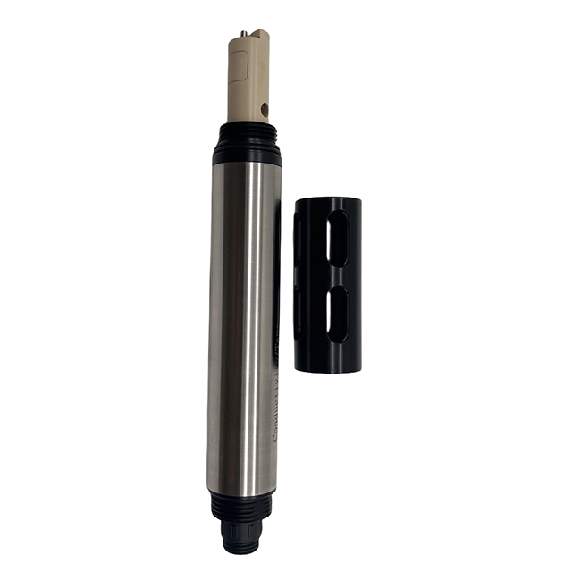
Sometimes, contacting sensors fail entirely. Ultra-high ranges or heavily fouling environments destroy standard metal electrodes. In these scenarios, you must abandon contacting technology. You transition to toroidal sensors. These inductive sensors use electromagnetic coils encased in durable plastics. They have no exposed metal. They excel in dirty water, chemical slurries, and severe wastewater applications where traditional probes would foul within hours.
Selecting the physical probe is only the first step. You must evaluate the supporting technology. Raw conductivity data changes based on thermal fluctuations. Conductivity typically rises by about 2% for every single degree Celsius increase. Therefore, uncompensated raw data provides useless information for process control.
You need Automatic Temperature Compensation (ATC). An effective EC water sensor integrates a Pt100 or Pt1000 temperature element. This element measures fluid temperature simultaneously. The transmitter then normalizes the final reading to a standard 25°C baseline. This ensures consistent data regardless of seasonal temperature shifts.
Material compatibility also dictates long-term success. You must match the wetted parts to the process fluid. Ultrapure systems often require Titanium or 316L Stainless Steel. These metals prevent contamination. Corrosive wastewater requires chemical resistance. CPVC, PTFE, or Graphite bodies survive harsh acidic or basic environments.
Finally, consider how the sensor communicates. Isolated data helps no one. You must transition your setup into active online conductivity monitoring. Modern plants require seamless integration. Evaluate whether your PLC or SCADA system needs analog 4-20mA signals or digital Modbus RTU outputs. IoT-ready digital sensors streamline calibration and provide advanced diagnostics directly to your control room.
Even the best sensor fails if installed incorrectly. Mounting location heavily impacts accuracy. Fluid flow must remain steady and fully cover the electrodes. Trapped air bubbles create major issues. If you install a low-range sensor at the highest point of an RO line, air accumulates. The sensor reads air instead of water. You see artificial low readings.
Conversely, avoid installing sensors in dead-legs. Stagnant water accumulates concentrated minerals over time. This causes artificial spikes in your data. Always ensure continuous, turbulent flow across the measurement surface. Using proper flowcells mitigates these common hydraulic errors.
You must also acknowledge the reality of fouling. Bio-fouling plagues cooling towers. Mineral scaling coats sensors in boiler systems. Sludge covers probes in wastewater applications. When deposits coat the electrodes, the sensor loses sensitivity. Calibration drift accelerates.
No sensor operates entirely maintenance-free. You need a solid mitigation strategy. Plan for regular cleaning cycles. For continuous streams, use bypass loops. A bypass allows technicians to isolate the sensor without shutting down the main pipe. Alternatively, specify retractable probe designs. These mechanisms let you safely withdraw the sensor under pressure for quick cleaning and calibration.
Engineering teams need a repeatable method to choose the right equipment. Follow this logical progression to specify an effective industrial EC sensor for your facility.
Define the Process Extremes: Do not just look at normal operating conditions. Document the baseline range. Then, record potential peak upset conditions in µS/cm or mS/cm. Your sensor must survive the worst-case scenario without saturating.
Select the Measurement Technology: Evaluate your fouling risk. Choose a contacting sensor if the water remains relatively clean. Select an inductive or toroidal sensor if you expect heavy sludge, oils, or extreme chemical concentrations.
Define Form Factor and Integration: Map out the physical installation. Specify the required insertion depth. Confirm pipe thread sizes. Check maximum pressure and temperature ratings. Finally, align the transmitter communication protocols with your existing control architecture.
Take actionable steps during procurement. Do not simply accept the lowest upfront unit cost. Request calibration certificates from the manufacturer. Ask for lifecycle data in similar applications. Prioritize long-term viability and data reliability over initial hardware savings.
Selecting the right monitoring equipment remains a strict exercise in matching operational ranges with sensor geometry. You cannot force a single K-factor to measure both pure RO permeate and harsh chemical effluent. Engineers must prioritize application alignment above all else.
Define your process extremes clearly. Protect your data through automatic temperature compensation. Plan for inevitable maintenance by installing bypass loops or retractable fixtures. These steps guarantee reliable, actionable data for your facility.
Take time to audit your current measurement points. Consult with an application engineer to verify your selections. Review technical data sheets carefully. Use proper product selection tools to map your exact process parameters to a specific, highly optimized sensor model.
A: No. These applications require completely different physical designs. RO water demands a low cell constant (K=0.01) to detect minute ion changes. Wastewater requires a high cell constant (K=10.0) or toroidal technology to prevent electrode saturation. Using one sensor for both guarantees inaccurate data.
A: Fluid conductivity increases by approximately 2% for every 1°C rise in temperature. Uncompensated readings fluctuate wildly as processes heat or cool. You must use sensors equipped with integrated temperature elements (like a Pt1000) to normalize all readings to a standard 25°C baseline.
A: Contacting sensors expose metal electrodes directly to the fluid. They offer high precision for clean water. Toroidal sensors use electromagnetic induction through encased plastic coils. They have no exposed metal. They resist fouling and excel in dirty, corrosive, or high-range wastewater applications.
A: Calibration frequency depends entirely on the process environment. Harsh wastewater applications may require monthly cleaning and calibration due to severe fouling. Conversely, sensors in highly controlled, clean RO systems might only need annual verification. Monitor data drift to establish your optimal schedule.