Views: 0 Author: Site Editor Publish Time: 2026-06-03 Origin: Site

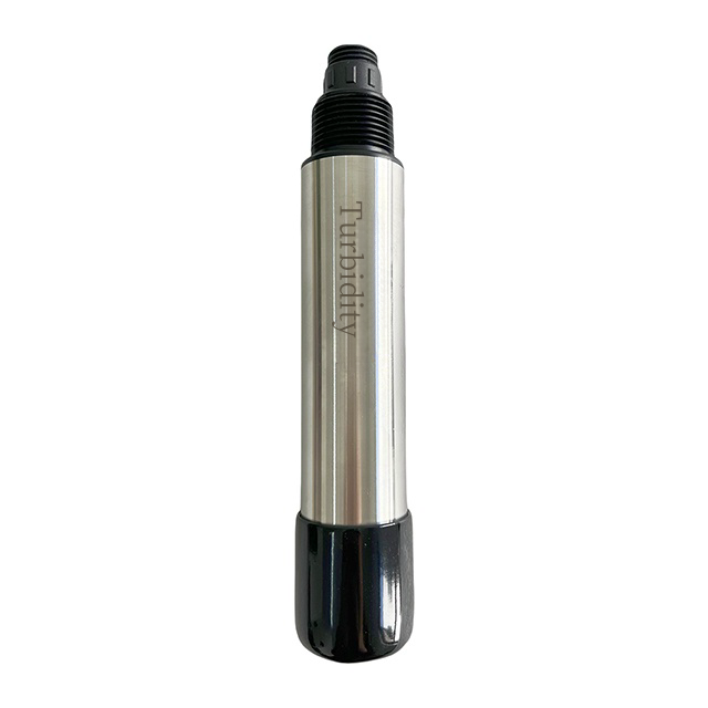
Continuous turbidity monitoring presents severe operational challenges in highly variable water treatment environments. Plant operators constantly battle fluctuating conditions, managing everything from pristine effluent streams to high-load sludge processing. You need equipment capable of adapting to these massive swings without losing precision. A 0-4000 NTU Water Turbidity Sensor serves as the baseline requirement for facilities demanding single-device versatility. It reliably captures extreme high-range solids while maintaining strict low-range accuracy. Relying on narrow-range monitors often invites regulatory compliance risks and process inefficiencies. This guide systematically unpacks the engineering fundamentals behind modern optical sensors. We will explore critical evaluation criteria, physical installation realities, and digital integration strategies. System integrators and water plant engineers will learn exactly how to select the right optical sensor for their toughest industrial applications.
Measurement Standard: High-range sensors utilizing 90° nephelometric scattering and near-infrared (850nm/880nm) light comply with ISO 7027 while eliminating color interference.
Maintenance Mitigation: Automatic cleaning (wiper) systems are non-negotiable for continuous monitoring in 100+ NTU environments to prevent biofouling and data drift.
System Integration: Modern sensors must support direct digital outputs (RS485/Modbus) for seamless SCADA integration alongside other parameters.
Calibration Reality: 0-4000 NTU models require segmented slope calibration (e.g., using Formazin) and specific physical installation to avoid bubble-induced data distortion.
Inconsistent turbidity readings plague many water treatment facilities. Engineers frequently encounter mismatched data across different vendor equipment. You often see severe interference when measuring colored water samples, particularly in industrial effluent. Dark or heavily tinted liquids absorb visible light. This absorption skews traditional optical measurements and generates falsely low turbidity readings. You need a standardized technological approach to solve this fundamental business problem.
The 90° nephelometric scattering light principle provides the necessary foundation for quantifying suspended solids. Instead of measuring how much light passes straight through a sample, a nephelometer measures light scattered at a 90-degree angle by suspended particles. More particles cause more scattering. This right-angle measurement drastically improves sensitivity at lower ranges while remaining robust at higher concentrations. It serves as the core technology required for reliable performance.
Optical design plays a vital role in executing this measurement accurately. Modern high-range sensors rely on 850nm or 880nm near-infrared (NIR) LED light sources. These specific wavelengths are invisible to the human eye. Near-infrared light objectively cancels out sample color interference because dissolved colors do not absorb NIR light the way they absorb visible white light. This design strictly complies with the international ISO 7027 standard. Furthermore, these NIR sensors reject ambient stray light effectively, ensuring your readings remain stable regardless of external lighting conditions.
You should also look for advanced architecture when evaluating sensor capabilities. Some elite models feature dual-light source, eight-beam systems. These sophisticated setups provide internal compensation for high-turbidity attenuation. When turbidity exceeds 1000 NTU, light loses intensity rapidly as it travels. Multiple beams calculate the signal loss and automatically correct the measurement. This self-compensating design guarantees pinpoint accuracy even in thick sludge applications.
Hardware durability defines the lifespan of any submerged instrument. You cannot place fragile plastics in corrosive or abrasive media and expect longevity. We highly recommend specifying sensors built from SS316L (stainless steel) and POM (polyoxymethylene). SS316L provides exceptional resistance against chlorides and industrial chemicals. POM delivers high mechanical strength for the sensor head. The entire housing must carry a strict IP68 waterproof rating. This rating ensures the internal microprocessors remain completely dry during continuous, deep-tank immersion.
You must also evaluate accuracy across different measurement tiers. A high-range sensor spans from nearly pure water to thick sludge. Buyers should never accept a single, blanket accuracy percentage for a 0-4000 NTU device. You need segmented accuracy profiling. A well-engineered sensor maintains tight tolerances at the low end while allowing acceptable proportional deviation at the high end. Below is a standard segmented accuracy profile you should expect.
Turbidity Range (NTU) | Typical Accuracy Standard | Common Application Scenario |
|---|---|---|
0 - 10 NTU | ±0.1 NTU | Post-filtration effluent, clean water discharge |
10 - 100 NTU | ±2% of reading | Raw surface water intake, secondary clarifiers |
100 - 4000 NTU | ±5% of reading | Aeration basins, heavy industrial wastewater, sludge |
Furthermore, auto-cleaning mechanisms are an absolute necessity in these high-range environments. Biological fouling and particulate buildup act as the primary causes of sensor drift. Algae and sticky organics coat the optical lens rapidly. Once the lens clouds over, the sensor incorrectly registers the dirt as suspended solids in the water. This forces technicians into a cycle of constant manual cleaning.
You can eliminate this burden by selecting sensors equipped with mechanical wiper solutions. A built-in motor drives a specialized brush across the sapphire optical window. Modern systems allow you to program these sweep cycles anywhere from 1 to 30,000 minutes based on site conditions. A standard 4-pass brushing action reliably sweeps away stubborn biofilms before they harden. This OPEX-reducing feature drastically minimizes manual site visits. It keeps your plant running autonomously and protects the integrity of your continuous data.
Continuous flow monitoring presents a harsh implementation reality. Engineering studies indicate optical sensors are highly susceptible to macro-bubbles and stray light. A passing air bubble reflects the infrared beam identically to a solid particle. This generates a massive, artificial spike in your data. Ambient sunlight hitting an outdoor tank can also blind the optical receiver. You must control the physical installation environment to achieve reliable results.
Effective installation strategies prevent these distortions entirely. Consider these key deployment methods:
Immersion Orientation: When deploying sensors in open tanks, never point the lens straight upward. Settling debris will bury the optics. Point it downward at a 45-degree angle. This orientation allows debris to fall past the lens while encouraging trapped air bubbles to float away naturally.
Inline Pipe Placement: If mounting the sensor directly into a flowing pipe, avoid the absolute top or bottom of the pipe. Air accumulates at the top, and heavy sediment drags along the bottom. Install the probe at the 3 o'clock or 9 o'clock position for the cleanest sample flow.
Flow Cell Utilization: High-velocity pumped lines create severe cavitation. In these scenarios, you must use a dedicated debubbling chamber or a bypass flow cell. These chambers slow the water velocity down. They allow entrained air to escape before the sample reaches the sensor head.
Beyond bubbles, you must acknowledge realistic limits on application environments. Optical lenses demand adequate protection. They remain vulnerable to severe mechanical abrasion from heavy sand. You must also avoid environments saturated with strong acids and peroxides. These aggressive chemicals can degrade the epoxy seals surrounding the lens window. By understanding these vulnerabilities, you prevent premature equipment failure and secure long-term measurement stability.
Modern industrial facilities rely entirely on centralized data. You cannot manage a plant efficiently if your sensors operate in isolated silos. When evaluating equipment, you must prioritize connectivity requirements. A professional sensor needs built-in RS485 communication utilizing the Modbus RTU protocol. It should also offer traditional 4-20mA dual outputs for legacy compatibility. These industrial standards ensure your data travels reliably across long cable runs without signal degradation.
Direct-to-PLC architecture offers tremendous benefits. Older analog sensors require expensive intermediate transmitters to process raw signals. Digital sensors contain built-in microprocessors right inside the probe. They process the optical data locally and send a clean, standardized digital value directly to your Programmable Logic Controller (PLC). This modern architecture eliminates the need for bulky intermediate controllers. It streamlines your wiring, simplifies troubleshooting, and reduces hardware complexity.
A high-range turbidity unit rarely operates alone. It acts as the backbone of a comprehensive monitoring array. Facilities achieve holistic monitoring by networking multiple smart sensors on a single Modbus chain. You can easily integrate it with a Water pH Sensor to track acid-base shifts in your effluent. You might add a Dissolved Oxygen Sensor to optimize blower speeds in aeration basins. Bringing all these digital probes into a unified PLC dashboard creates a powerful Multiparameter Water Quality Sensor network. This unified approach delivers complete, real-time wastewater profiling for advanced process automation.
Routine maintenance ensures your data remains legally and operationally valid. While auto-wipers prevent daily fouling, long-term optical drift is inevitable. You must execute standard calibration procedures periodically. This process involves a critical distinction between zero-point offset and slope calibration.
For the zero-point offset, you submerge the cleaned sensor into ultra-pure, bubble-free distilled water. This tells the microprocessor what "absolute zero" looks like. Next, you perform the slope adjustment using standard Formazin solutions. Because a 0-4000 NTU sensor has such a massive range, you often need multi-point slope calibrations. You might use a 100 NTU solution to anchor the low end and a 2000 NTU solution to anchor the high end. This creates a precise measurement curve.
Operators frequently want to convert NTU directly into Suspended Solids (SS) measured in mg/L. You must understand that converting NTU to SS requires site-specific empirical calibration. Turbidity measures scattered light, while SS measures physical weight. You cannot apply a universal conversion formula. To build a localized correlation, you must record the optical NTU data and simultaneously draw physical water samples. You then process these samples through laboratory dry-weight sludge testing. Once you map the NTU readings against the lab dry-weights, you achieve high-accuracy localized monitoring tailored to your specific facility's particle density.
Data retention capabilities simplify lifecycle management significantly. Older probes lose their calibration data when disconnected from power. You should prioritize sensors that store calibration coefficients directly on their internal microprocessor chips. This feature allows technicians to calibrate a spare probe in the comfort of a laboratory. They can then take it to the field and hot-swap it with the active probe. The plug-and-play design ensures zero plant downtime during routine maintenance cycles.
Selecting a versatile 0-4000 NTU optical monitor requires a careful balance of engineering features. You must weigh optical sophistication against physical resilience. Your ideal shortlisting logic should demand ISO 7027 compliance, 880nm near-infrared technology, and automated mechanical wipers wrapped in an SS316L housing.
Before requesting vendor quotes, technical buyers should execute a few specific next steps. Audit your intended installation environment closely. Identify potential bubble risks in your piping or open tanks. Finally, determine your exact PLC and SCADA integration requirements to ensure seamless digital handshakes across your plant.
Prioritize 90° near-infrared scattering to eliminate color and ambient light interference completely.
Demand integrated auto-cleaning wipers to combat biofouling in harsh wastewater conditions.
Utilize direct Modbus RTU communication to streamline your SCADA architecture.
Execute site-specific dry-weight lab testing if you intend to convert NTU data into Suspended Solids (mg/L).
Install sensors strategically to prevent bubble accumulation on the optical window.
A: Data drift primarily stems from biological fouling or algae accumulation on the optical lens. It also occurs when micro-bubbles pass through the sample stream, reflecting light artificially. Finally, long-term degradation of the internal LED light source gradually reduces optical intensity over several years.
A: No. Online sensors provide continuous real-time trends required for SCADA systems and process automation. However, a Portable Water Quality Sensor remains absolutely essential for spot-checking plant zones, conducting multi-site audits, and scientifically verifying the calibration accuracy of your fixed online units.
A: Replacement frequency depends heavily on the abrasiveness of your specific media. Routine inspection every 6 to 12 months is the industry standard. Worn or stiff wiper blades will eventually smear dirt across the optical window rather than cleaning it effectively.
A: It infers Suspended Solids based on turbidity (NTU) values. However, it requires site-specific empirical calibration against laboratory dry-weight tests. Because particle size, color, and physical density vary wildly by facility, you must establish a localized correlation curve for accurate mg/L outputs.