Views: 0 Author: Site Editor Publish Time: 2026-07-05 Origin: Site

Industrial water monitoring requires strict compliance and highly precise process control. Facilities simply cannot afford unexpected downtime in their fluid management systems. Choosing the right sensor goes far beyond basic measurement capabilities. You must ensure seamless integration compatibility and effectively manage predictable maintenance cycles. Selecting substandard equipment quickly leads to costly false readings and operational blind spots.
We bypass generic definitions of electrical conductivity in this article. This guide provides a direct, evidence-based evaluation framework. Engineers and procurement teams will learn exactly how to shortlist sensors effectively. You will discover the best practices for specifying instrumentation in harsh, continuous monitoring environments. By applying these criteria, you protect your infrastructure and guarantee accurate data collection across all fluid types.
Application Dictates Technology: High-salinity or heavy-chemical applications demand different electrode architectures than ultrapure water systems.
Integration is Critical: A high-end sensor is useless if it causes ground loop issues or fails to communicate reliably with existing PLCs.
Sourcing Strategy: Procuring directly from a dedicated water conductivity sensor factory often yields better technical support, custom calibration options, and supply chain reliability.
Different industrial settings expose sensors to unique physical and chemical stressors. You cannot deploy a universal probe across all fluid types successfully. Engineers must match the probe's architectural design to the specific process environment. Failure to align the sensor type with the fluid characteristics leads to rapid degradation.
Saltwater environments degrade standard metals rapidly. Aquaculture setups and high-salinity industrial processes demand highly corrosion-resistant materials. You should look for wetted parts made from Titanium or PEEK. These materials prevent rapid degradation while supporting broad measurement ranges. High salinity generates strong electrical currents in the fluid. The sensor must handle these elevated ionic concentrations without suffering from galvanic corrosion. Proper material selection ensures long-term stability in continuous submersion.
Common Mistake: Procurement teams often select standard 316L stainless steel for brine applications. Stainless steel inevitably suffers from pitting corrosion in high-chloride environments. This misstep leads to premature sensor failure and unexpected replacement downtime.
Wastewater streams and chemical baths introduce harsh acids, bases, and suspended solids. You must focus on extreme pH tolerance and robust anti-fouling designs. The ideal water quality conductivity analyzer here prioritizes self-cleaning capabilities. Ruggedized housing is absolutely essential. Heavy chemical applications often cause scale buildup on electrodes. This scaling insulates the metal and skews readings lower. You need sensors designed to shed debris or withstand frequent chemical wash-downs.
Best Practice: Always specify flush-mounted electrodes for heavy effluent streams. Flush mounts prevent fibrous debris from snagging on the sensor body. This physical design choice reduces your manual cleaning frequency significantly.
Pharmaceutical manufacturing and industrial boiler feeds rely on ultrapure water. These environments strip away nearly all conductive ions. Detecting minute ionic changes safely requires highly sensitive equipment. You must use low-range cell constants, such as K=0.01. These specialized probes detect trace contaminants before they cause boiler scaling or compromise pharmaceutical batches. Standard sensors simply cannot read the near-zero conductivity of ultrapure streams accurately.
Choosing between electrode configurations remains a critical engineering decision. The wrong choice guarantees constant recalibration and process errors. We must evaluate both technologies based on their physical operating principles. You must select the configuration tailored to your fluid's complexity.
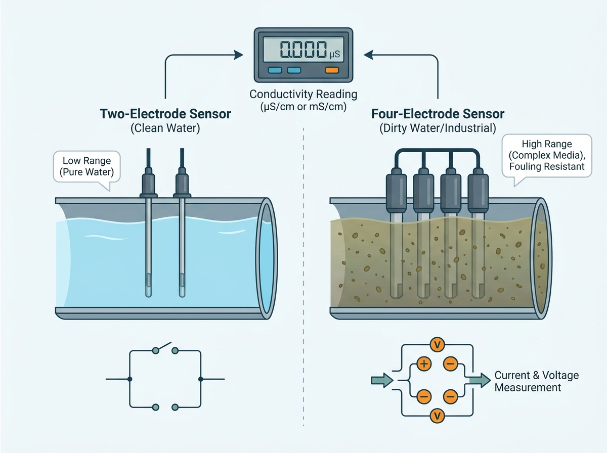
Two-electrode designs represent the traditional approach to conductivity measurement. They pass an alternating current between two parallel plates or pins. The system measures the resistance between these two points to calculate conductivity.
Best for: Clean water and low conductivity environments. Reverse osmosis (RO) systems and pure water loops benefit greatly from this simple, effective design.
Limitations: These probes remain highly susceptible to polarization errors. High-conductivity fluids cause ions to accumulate on the electrode surface quickly. This accumulation creates an opposing electrical field. The sensor then outputs artificially low readings. Fouling in dirty water also insulates the two pins, rendering the data useless.
Advanced applications require a more robust measurement technique. The four-electrode conductivity sensor solves the inherent physical flaws of traditional two-pole designs.
Best for: Complex, industrial, or high-range applications.
Engineering Reality: This design uses two outer electrodes to maintain a constant alternating current. Two inner electrodes then measure the resulting voltage drop. The inner pins draw almost no current themselves. This architecture inherently compensates for electrode fouling and polarization. You get superior long-term accuracy in challenging, dirty media.
Comparison Chart: Sensor Configurations
Feature | Two-Electrode Design | Four-Electrode Design |
|---|---|---|
Ideal Environment | Clean, ultrapure water | Dirty, high-salinity, complex fluids |
Fouling Resistance | Low | High |
Polarization Risk | High in concentrated media | Negligible |
Measurement Range | Narrow (Low EC only) | Broad (Mid to High EC) |
Procurement teams must look beyond basic spec sheets. An industrial-grade online ec sensor requires careful alignment with your physical plant infrastructure. Evaluate these core technical criteria before making a final vendor selection.
The cell constant dictates the probe's measurement sensitivity. You must align the K-factor with the expected conductivity range of your process fluid. Mismatching the K-factor guarantees blind spots in your data.
K=0.01: Use this for ultrapure water, boiler feed, and pharmaceutical water-for-injection.
K=0.1: Select this for moderately clean water and reverse osmosis system outputs.
K=1.0: This serves as the general-purpose standard for tap water, cooling towers, and mild wastewater.
K=10.0: Deploy this for highly concentrated chemicals, saltwater, and heavy industrial effluents.
You must evaluate all wetted parts for chemical and thermal resistance. CPVC works exceptionally well for general use and ambient temperatures. 316L Stainless Steel provides excellent durability for high temperature and high-pressure lines, provided the fluid lacks high chlorides. Aggressive chemicals require advanced polymers. PEEK and PTFE offer the highest resistance against strong acids and corrosive bases.
Fluid conductivity remains highly temperature-dependent. A slight temperature shift dramatically alters the raw conductivity reading. Your chosen sensor must include rapid, accurate Automatic Temperature Compensation (ATC). Look for integrated Pt100 or Pt1000 RTD elements. These internal temperature sensors adjust the raw reading back to a standard 25°C reference point instantly.
Best Practice: Ensure the RTD sits as close to the measurement electrodes as possible. Deeply embedded RTDs suffer from thermal lag. This lag causes delayed compensation and temporary data spikes during rapid fluid temperature changes.
The physical shape of the probe determines how you install it safely. Inline pipe insertion works best for continuous flow monitoring in closed loops. Submersible probes hang securely inside deep tanks or open effluent channels. Sanitary flange connections are mandatory for food, beverage, and pharmaceutical lines to prevent bacterial growth. You must match the form factor to your existing pipe fittings perfectly.
Lab performance rarely matches field reality. Industrial plants present harsh physical conditions and complex electrical networks. You must plan for these variables during the initial engineering phase. Proper installation guarantees longevity.
Physical constraints often dictate installation success. Tank-mounted installations require careful positioning. You must avoid areas of severe agitation where trapped air bubbles gather around the electrodes. Air bubbles displace water and cause artificial drops in conductivity. Dead zones pose another severe risk. Fluids in dead zones do not circulate. This stagnation skews readings away from the actual bulk fluid concentration. Install probes in active flow paths to ensure representative sampling.
Your water ec monitoring probe must communicate flawlessly with your control architecture. Ensure the transmitter supports robust industrial protocols. Analog 4-20mA signals remain the standard for simple, long-distance transmission without signal degradation. RS-485 Modbus RTU provides rich digital data for modern digital systems, allowing multi-drop networking. Direct integration into PLCs, SCADA, or existing controllers requires matching these signal types exactly.
Electrical interference plagues many industrial plants. Pumps, motors, and variable frequency drives generate stray voltages. These stray currents travel through the process fluid and enter the sensor. This creates a destructive ground loop. Ground loops cause erratic, fluctuating conductivity readings that confuse automated dosing systems.
Common Mistake: Wiring non-isolated sensors directly into a main PLC rack often causes system-wide electrical noise. You must use galvanically isolated transmitters. Isolation blocks stray currents and ensures the PLC receives a clean, accurate signal.
We must transparently assess required cleaning intervals and calibration frequency. No sensor is entirely maintenance-free. Dirty applications coat electrodes in biological slime or mineral scale. You must establish a routine cleaning schedule based on historical fouling rates. Factory managers should monitor sensor drift systematically to determine the optimal calibration frequency. Proactive maintenance prevents sudden process failures and keeps quality control intact.
Supply chain strategy impacts project success heavily. Purchasing an industrial conductivity meter directly from the manufacturer offers distinct technical and logistical advantages. You bypass legacy procurement bottlenecks.
Working directly with a manufacturer reduces lead times significantly. You bypass regional distributors and avoid their associated retail markups. This direct pipeline lowers unit costs for bulk deployments across large facilities. Direct communication also eliminates the "telephone game" when discussing complex technical specifications. You speak directly to the engineers who designed the equipment.
A dedicated water conductivity sensor factory provides deep customization options. Factories can adjust cable lengths to fit exact conduit runs on your factory floor. They modify connector types to match proprietary machine designs seamlessly. Engineers can request specific K-factors tailored to unique plant layouts or specialized media. Off-the-shelf vendors rarely offer this level of mechanical flexibility.
Direct sourcing guarantees access to recent, traceable calibration certificates. Stale inventory from a local distributor might sit on a warehouse shelf for years. Freshly calibrated units ensure immediate accuracy upon installation. You also gain a direct line-of-sight to the factory engineering team. This access proves invaluable for complex post-sale troubleshooting, custom firmware updates, and rapid warranty support.
Selecting the proper conductivity instrumentation requires a structured, logical approach. You cannot rely on guesswork when facility uptime is on the line. Follow a strict evaluation framework to ensure success.
Shortlisting Logic: Base your final decision on fluid characteristics first. Range and corrosiveness dictate the baseline technology. Consider integration needs like PLC protocols and mounting hardware second. Evaluate the base unit cost only after satisfying the engineering requirements.
Next Steps: Consult directly with technical sales teams to discuss your specific fluid dynamics. Request trial units for pilot testing in your actual plant conditions. Verify protocol compatibility with your internal system integrators before placing bulk orders.
A: You must match the K-factor to your fluid's expected conductivity. Use K=0.1 for highly pure water and low conductivity applications. Select K=1.0 for mid-range fluids like tap water and general wastewater. Choose K=10.0 for highly concentrated environments like saltwater or industrial chemical baths. Proper matching ensures the sensor measures accurately within its optimal range.
A: Calibration frequency depends entirely on water quality, fouling rates, and specific regulatory requirements. Clean water applications might only need calibration every six months. Harsh industrial uses typically require calibration every one to three months. You should monitor the sensor for reading drift to establish a customized, reliable maintenance schedule for your specific facility.
A: Yes, but it requires a conversion factor. EC is the true, raw measurement of electrical current passing through the fluid. TDS is a calculated estimate. You typically multiply the EC value by a factor between 0.5 and 0.7 to find the TDS. The exact factor depends on the specific types of dissolved ions present in your water.
A: Several field issues cause erratic readings. Trapped air bubbles inside the measurement cell displace fluid, causing drops to zero. Severe mineral scaling insulates the electrodes, preventing current flow and causing downward drift. Finally, severed probe cables or moisture ingress at the connector block ruin signal transmission entirely. Always inspect the physical probe first.